Friday 18 September 2015

Level and Obstruction for PDMS Primitives

Level
Level Attribute is specified as two Numbers, representing the inclusive range in which that element will be drawn or shown.
In Design, Only Primitives whose Level included by REPRESENTATION Command will be shown.

For Nozzles and Piping Components Level Ranges are specified in Catalogue.
If range Level specified by Representation command is 0 6 then all primitives whose Range Level is 7 or more to 10 will be not be shown or drawn.

Normally we specify, Level range 7-10 for Insulation while Level 8-10 for Obstruction. Because of which we don't see Insulation and Obstruction in Display.
To see Insulation or obstruction, we need to force system to override current representation setting and show Insulation and Obstruction.
Level range may vary from company to company depending their own set standard.

To check Representation
Go to Settings, select Graphics

It opens form, select Representation Tab to Check above setting

Image 1. Representation Setting

Following Commands maybe useful 

To check Representation Level
Q REPRE Level

To Switch on Insulation or Obstruction on Display
REPRE INSU ON OBST ON
REPRE UPDATE

To Switch off Insulation or Obstruction  on Display
REPRE INSU OFF OBST OFF
REPRE UPDATE


Obstruction
Obstruction Attribute is used to Indicate Clash Detection Facility whether a Primitive Should be considered as 'Hard' or 'Soft' Obstruction or No obstruction at all. Obstruction can be specified HARD, SOFT or NONE, or Alternatively they can be specified by numerals as follows :

Hard Obstruction - 2
Soft Obstruction - 1
No or Ignore Obstruction - 0

Specifying Through Command Line
Obstruction Hard or Obstruction 2
Obstruction None or Obstruction 0

Equipment Modelling : Primitive Box

BOX
Box is well known to all of us. It has three dimensions (Xlength, Ylength, Zlength) which needs to be defined in PDMS to model it.
By default, Orientation of Box is Y is N and Z is U.

P-Point Configuration
Box has Seven P-points, one p-point on each face with direction perpendicular to face and Origin (P0) at Center. 
Each P-point has attributes Direction and Position.
All dimensions given are measured half on either side of origin in respective axis direction (E-N-U).

Image 1 P-Point Configuration

We can Model box in PDMS by two methods :
1. By Graphical Method
2. By Command Line

1. Graphical Method
To start with Box Modelling, Equipment Application shall be selected.
Select Equipment or Sub-Equipment under which you want to model Box.

Go to Create Menu, select Primitives Option

Image 2 Create PrimitivesOption

It will open Primitive form, which lists all Primitives available in PDMS.

Image 3 Primitives Form
 Select Box Option, it will open following form, to input Dimensions of Box.

Image 4 Setting Dimensions and Level

Click on Parameters Option to Check Box Parameters. (Xlength, Ylength, Zlength)

Image 5 Box Parameters

Here you can notice that Ylength is North-South Direction, Xlength is in East-West Direction and Zlength is in Up-Down Direction. So in order to avoid orientation of Box at later stage, Box dimensions shall be input accordingly.

Once you enter Dimensions of Box, Set Level and Obstruction Attribute for Box.

Click on Create button, it will create Box with given Dimension and displays additional options to set other attributes.


Image 6 Specifying Box Attributes


Datum
Select Datum or Reference Point on Box, which will be used to Position Box.
Any P-point on Box can be selected, By default Datum is set to Origin of Box (P0).

Position
Enter 3D coordinates (ENU) to explicitly position box at specified position with respect to owner (Default) or given element.

Rotate
Enter angle by which primitive shall be rotated about origin and Select Direction about which it shall be rotated. 

Alight with P-point
It allows you to orientate Box in direction with Selected P-point from display. it basically connects Origin of Box to Selected P-point.

Clicking Next Button Completes Box Modelling.


Image 7 Box in PDMS

Modify Box
Go to Modify, Select Primitives Option.
Similar form as that of Box creation will appear, Change attributes wherever required.

Negative Box
Negative Box is nothing but hollow box.
For Modelling Negative Box, From Primitives Form (see Image 3) select Switch to Negative Primitives option, Select Negative Box and set all parameters and Attributes similar way as stated for creating Box.

2. Command Line Method
Following Attributes of Box and Negative Box must be set in order to correctly model it in PDMS.

Position, Orientation, Level, Obstruction, Xlength, Ylength, Zlength.

Creating Box/Negative Box
New Box                                   - Creates Box
New NBox                                 - Creates Negative Box
Xlength 200 Ylength 500 Zlength 300
Level 0 10
Obstruction 2

Position and Orientation
Position at E 0 N 500 U 100     - Positions Origin of Box at given position
Position at id @                        - Positions Origin of Box to Origin of Selected Primitive
Position at idp @                      - Positions Origin of Box to Selected P-point

Orientate Y is E and Z is U 
Rotate About E by 45               - Orientates Box through Origin about E by 45
Rotate Thro P3 About S By 45 - Rotates Box through P3 about S by 45

Connect IDP @ to IDP @         - Orientates Box so that Selected P-point of Box gets connected to Selected P-point on another element.

(Note :  Not all Commands are covered here. Use Command whichever is useful depending upon requirement).

Sunday 13 September 2015

Equipment Modelling in PDMS

To start with Equipment Modelling, you should go to Equipment Application.

How to go to Equipment Application
Go to Design Menu then select Equipment from drop down.


Switching to Equipment Application


Modelling Equipment in PDMS
In PDMS, Equipment can be modelled in Two ways 
1. Using Primitives
2. Using Standard Equipment Template

Before creating equipment, you must be at zone level in hierarchy. Optionally under Equipment, Sub-Equipment (SUBE) can be created to classify different parts of Complex equipment, which gives user flexibility to work on specific parts in later stage.

Let's see First Method....

Equipment Modelling using Primitives.
In this Method, Equipment will be modelled using combination of Primitives, which are arranged in such a way that they physically model the real life object to some degree.

Primitives are nothing but basic geometric shapes which forms part of Equipment.
Geometry of Primitives is totally user defined, there is no link with Catalogue database.
Primitives can be modelled under Equipment and Sub-Equipment.

Here is list of all Primitives available in PDMS
1. BOX
2. CYLINDER
3. CONE
4. SNOUT
5. PYRAMID
6. CIRCULAR TORUS
7. RECTANGULAR TORUS
8. DISH
9. SLOPED CYLINDER
10. EXTRUSION
11. SOLID OF REVOLUTION

Nozzles also form part of Equipment Modelling,unlike Primitives, Nozzles can be directly selected from Catalogues Available in Project. Nozzles takes thickness, diameter and Bolt settings from catalogue while height needs to be entered by user.

It is Completely User judgement which kind of Primitive should be used to Model equipment.
In general, Primitives shall be selected in such way that Equipment modelling becomes easier to create or Modify.

We will see each primitive in Detail in next posts.....


Saturday 12 September 2015

Design Module

Design Module is Main constructor Module in which Complete Chemical Process Plant is 3D modelled. User selects required components from available specifications and catalogues and positions them as per engineering design. 3D model data is stored in Design database for individual site created. Design Module provides facility to check elements for Clashes, Reporting to produce various design documents for quality checks, Material Takeoff and Preview of Piping Isometrics.

In Design Module, all the Functions related to specific discipline are grouped under Applications such as Equipment, Pipework, etc. User need to Select appropriate Application in order to work, so that relevant Functions for particular discipline will be made available.

Applications in Design Module 

1. General
This Application Provides Functions which are common to All disciplines, such as Creation of Site/ Zone, Copying or Deleting Elements.

2. Equipment
This Application Provides Functions which are Useful for Equipment Modeling, such as to Create, Modify Equipment or Primitives.

3. Pipework
This Application Provides Functions which are Useful for Pipe Modeling, Such as to Create, Modify, Connect Pipe or Piping Components.

4. Cable Trays
This Application Provides Functions which are Useful for Cable Tray Modeling, Such as to Create, Modify Cable Trays.

5. HVAC Designer
This Application Provides Functions which are Useful for HVAC Modeling, Such as to Create, Modify HVAC and its Elements.

6. Structures
Structures has Four Applications which are as follows :
I. Beams and Columns 
Provides Functions to Create or Modify Sections

II. Panels and Plates
Provides Functions to Create or Modify Panels or Plates

III. Walls or Floors
Provides Functions to Create or Modify Walls or Floors

IV. Access, Stairs and Ladders
Provides Functions to Create or Modify Access, Stairs , Ladders

7. Design Template
This Application Provides Functions to Create PDMS Element using Standard Design Template which already created by Administrator.

8. Cabling System
This Application Provides Functions to Create CableWays, Cables, Assigning Cable Material for Cables.

Before User starts creating or modifying any element, User must have read-write access to that element. if access not provided, user must request administrator for the same.

Following command maybe useful to find out this :

Q DBWRITE

if True  -  User Has read-write access to Database
if False - User do not have write access, User should request access to Administrator


Monday 7 September 2015

Reference Databases

1. CATALOGUE Database
Catalogue Databases are used in Paragon Module and maintained by PDMS Administrator. This Database holds information about Catalogue for standard components which are selected in Design Modules through Specification.
Catalogue of Component has Data related to its Dimensional Details, End Connections.
Catalogue Database also stores specification, Connection Compatibility information, bolt table, Nozzle Specification, specification for HVAC, Steel, Cable trays.
For any project, we can have Master Catalogues provided AVEVA. In addition to that project may contain catalogue created by Administrator based on Company Standards.

Typical Hierarchy for Catalogue Database


Fig. 1 Catalogue Database Hierarchy
Fig. 2 Catalogue Database Hierarchy
Unlike other databases, Catalogue database holds main administrative elements at same world level under same database. 
E.g. Specification world and Catalogue are world level elements which are in same database.

2. DICTIONARY Database
Dictionary Database is used in Lexicon Module. It holds data for User Defined Attribute (UDA) and User Define Element (UDET) created in that Project.

Typical Dictionary Database Hierarchy
Fig. 3 Dictionary Database Hierarchy

3. PROPERTIES Database
Properties Database is used in Paragon Module. Administrator can update content of this database. This database holds data about Material Properties, Pipe Temperature-Pressure Cast Data, Component data, Constraint Data, etc.

Typical Hierarchy of Properties Database
Fig. 4 Properties Database Hierarchy

Sunday 6 September 2015

Design and Drawing Databases

1. Design Database
Design Database Contains Data which holds information about 3D elements created in Design Module. It contains elements in particular hierarchy with all attributes of that element. User having read-write access to Design Database can create or Modify content of that database.
SITEs created in Design Module are linked to particular Design Database. One Design Database can own one or several sites depending upon requirement.

Design Database Stores Data created using following applications in Design Module :

1. Equipment
2. Pipework
3. Cable Trays
4. HVAC Designer
5. Structures
6. Design Template

Typical Hierarchy of Design Database:
Fig. 1 Design Database Hierarchy

Note : Equipment can directly own Primitives and Nozzle

Similarly, hierarchy for Structural Elements


Fig. 2 Design Database Hierarchy
In Design Database, SITE and ZONE are top most hierarchical Elements which are common for all elements.

2.    PADD Database
PADD – Production of Annotated and Dimensioned Drawings
PADD(Draft) Databases are used in Draft Module, which Holds data about Pictorial content of Drawings and Dimensional Information. it also holds information about Draft setup such as Sheet Libraries, Symbol Libraries, Isodraft Libraries, Label Libraries, Style Libraries etc.
Similar to Design Database, It also holds elements in Particular hierarchy.

Typical Hierarchy of Draft Database


Fig. 3 Draft Database Hierarchy


3.    ISOD (Fabrication or Spooler) Database
Fabrication or Spooler Database is used in Spooler Module. This database holds Information about Spool Drawings such as spools, Field, welds, joints, etc., which is used for fabrication purpose. 

Typical Hierarchy of Spooler Databse


Fig. 4 Spooler Database Hierarchy


Tuesday 1 September 2015

PDMS Databases

Introduction
For any PDMS Project, Every data related to that Project is stored in particular type of Database. Databases are created by administrator based on physical area or complexity of Plant at the time of Project setup. Databases can be included or copied from other Project also. These Databases can be found in xxx000 folder (xxx – Project Code). Each Module uses one or several databases to work on Project, if required databases are not found or user does not have access to those databases then Entry to that module will be prohibited and user will be directed to Monitor Module.
As per good practice, each discipline (such as Piping, Mechanical, etc.)  for particular process unit or construction unit should have separate database to work.

Database Elements

Before we proceed with databases types and Structure, understand following Fundamental Elements related to Databases:
Team – This Element owns database created in Project, Team can own one to several databases of same type or of different type. 
User – Member of Team, has Username and Password, has read or write access to database depending upon access right set by administrator.
User can be Free or General. Free User has access to All modules and can modify all Databases, while General Users can't enter restricted modules but can modify databases to which they have access as set by administrator.
MDB – Collection of DBs, normally it groups of all required databases for Project. Project must have at least one MDB. MDBs can be created for every user or for Units depending volume or Complexity of Plant. MDBs must contain reference databases which are  used by modules. E.g. MDB containing design Databases must Contain Catalogue database/s.
Database Access 
Databases can be accessed in UPDATE or MULTIWRITE access Mode. Access Mode is set at time of Database Creation, later it can be changed if required.
In UPDATE access Mode, only one user has write access to that database while others can access that database in Read only mode. 
In MULTIWRITE Access Mode , several users can write and read database at same time.
DESIGN, CATALOGUE, DRAFT and ISODRAFT, SYSTEM Databases are MULTIWRITE databases. 
In MULTIWRITE Databases, Claim Mode can be set to Implicit in which Database elements are claimed automatically whenever User modifies elements  or Explicit Mode in which Database elements need to be claimed first before user can start work on them.
Note : Only One User can work on same element or same part of Database at same time.
In order to Other User start working on same element, first user must release claim over that element.

Database Sessions
Session in PDMS is section of Database which holds data about work user has done till Savework or module change. work done in that session can be saved or discarded by user. whenever User switches Module or Saves work by SAVEWORK Command, session data will be stored to Database with Session Number. after that new pdms session will be created. Every database on which user works has separate Database session which can be saved by SAVEWORK Command. Sessions are useful for Backtracking and Merging databases as part of Maintenance activity for Project.

Database Functionality
DABACON
Database Constructor is system used by PDMS to construct, navigate, interrogate a database structure. DABACON instances are data objects which can be equipment or Primitive in PDMS, which are hold in particular hierarchy in Database, has set of attributes to define properties of items.
E.g. Equipment is significant element in PDMS which owns SUBE or Primitives such as BOX, CYLI, etc. , which has attributes such as Xlen, Ylen, Zlen to define geometry or properties of item.

The DABACON buffer is an area of data storage space within each module, reserved for holding pages of data which have been read from databases or which are to be written to databases. Data transfers between the databases and the module always take place in  exact multiples of one page.
The default buffer size is 5,120,000 words (20 Mbyte) for all modules.

Database Types
For any Plant Design Project, there are 10 different types of Databases which can be created depending upon requirement. Databases can be majorly classified as follows based upon the functionality.
1. Design and Drawing databases
    Design (DESI) Database
    Draft (PADD) Database
    Isodraft (ISOD) Database
    Schematic (SCHE) Database

2. Reference Databases
    Catalogue (CATA) Database
    Dictionary (DICT) Database
    Properties (PROP) Database

3. Administration Databases
    SYSTEM Database
    COMMS Database
    TRANSACTION Database

Thursday 20 August 2015

Getting Started: Introduction to PDMS

PDMS (Plant Design Management System) is 3D Design software package developed by AVEVA Group Plc (UK based Information Technology Company). PDMS provides various functions which are useful for Engineering, Design and Construction of Chemical Process Plants (both offshore and onshore Projects).

PDMS is Multi-User, Multi-Discipline 3D design tool which can be customized with PML (Programmable Macro Language) and C# to suit company or Project Requirements. PDMS Global allows big and complex projects to be divided over geographical regions/offices on which users can work concurrently from their respective locations depending upon scope of work agreed.

PDMS enables you to design 3D interactive computer model of Chemical Process Plant with full colour shaded representation. PDMS User selects and positions components from available catalogues. 3D Model becomes source of engineering data for all sections and disciplines involved in design project.
PDMS clash checking facility ensures clash free model to be generated to eliminate scope of error that could arise on site while construction. Reports can be generated from PDMS to perform quality check in design so unwanted errors could be avoided. 2D engineering drawings which are produced using PDMS, forms sharing links to transfer information from Design office to Construction site.

PDMS stores all kind of data in respective Database depending upon type of data to be stored. Databases are created by Administrator as per project requirements along with Users who will work on those databases with required access rights.

PDMS is split into a number of Modules which are used at different stages in Plant Design Process.

Availability of PDMS Modules differ depending upon type of license agreement.

In following section, we will discuss about PDMS Modules and their role/ Functionality in Plant Design Process.

1.  Design Modules

    I. DESIGN
Design is Main constructor Module in which Complete Chemical Process Plant is 3D modelled. User selects required components from available specifications and catalogues and positions them as per engineering design. 3D model data is stored in Design database for individual site created. Design Module provides facility to check elements for Clashes, Reporting to produce various design documents for quality checks, Material Takeoff and Preview of Piping Isometrics.
Design Module has Applications which provides suitable functions to work on particular discipline. E.g. Equipment, Piping, Cabling, etc.
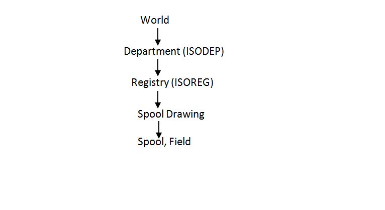
II. SPOOLER
Spooler is used for pipework spooling. In this Module, Pipework design can be split into logical sections (i.e. Spools) which are ready fabrication.  Spool data created in Spooler module can be output as Isometric Drawing using ISODRAFT Module.
  
2. Drafting Modules

I. DRAFT
In this Module, Fully dimensioned and annotated 2D drawings of 3D Model are created. Data required for creation of drawings is accessed through Design Database while rest of data is stored in Draft database. Like Conventional Engineering Drawings, User creates views to show particular area of 3D model in required direction. Dimensions and Labels are attached to design elements which are stored under respective view.

II. DIAGRAMS
This Module is used for creation of P&ID, HVAC and Cabling Diagrams. This Application uses AVEVA Design Platform GUI and Diagram Layouts are created using an Embedded Microsoft Office Visio drawing control. Data entered into this application is stored in Schematic Database.
This Module uses Diagram, Stencil and Template Path to create Diagram File. User need to select mode to work to create either P&ID/HVAC/Cabling Diagrams. Diagram files created in this module can be saved in binary format or XML format.

III. Schematic Model Manager
Schematic Model Manager is used to Import P&ID data from XML file into Schematic Database which can be viewed and Modified if required in later stage of Project.

3.  ISODRAFT
ISODRAFT is used to produce automatically annotated and dimensioned piping Isometric drawings along with Material list for that pipe. User need to select from Option file available for project working on, Option file can be customized to suit company or project requirements by administrator. ISODRAFT provides option to take MTO which can be saved to Text file for each Pipe, which can be later used to generate Bulk MTO for Plant.

4. Catalogues and Specification Management Modules

I. PARAGON
This Module Used for Creation and Modification of Catalogues which are referenced by Specification reference of Component. Administrator is directly responsible for Catalogue Creation, Modification.
Component Catalogue normally holds information about connection, Physical Shape, Obstruction and Bolting requirements.
Paragon also stores specification to be used for project, connection Compatibility information of Components, Material and Detailed description of components.

Catalogues must be setup properly in order to avoid any errors in 3D modelling.

II. SPECON
SPECON is Specification Constructor Module, which allows administrator to create or modify specification to suit Project requirement.

III. PROPCON
PROPCON is property Constructor Module, administrator create or modify properties database. Properties database hold information about properties of Component and materials which may be used for stress analysis, calculation of weights, Centre of gravity for components.

5. Project Administration Modules

I. ADMIN
ADMIN is main administrative module which plays important role in setting up Project, database creation, User Creation and access rights for Users. Depending Upon size and complexity of Plant, Plant is divided into individual areas (either on basis of Physical area or Design Area).  It allows administrator to setup fonts, Module definitions for Project.
ADMIN module provides important features which are useful for Project Maintenance such as compacting Database to reduce database size by removing unwanted data,  Upgrading PDMS Projects when database structure changes.

II. LEXICON
LEXICON is used to create User defined attributes. Every element in PDMS has set of attributes which can be set or read. Sometimes default attributes provided by AVEVA may not sufficient; in that case we may define our own attributes which can satisfy requirement which are called as User Defined Attributes. UDAs created in LEXICON are held in Dictionary database. Administrator can choose type of attribute, scope of attribute (e.g. Pipe, Equipment, etc.) and maximum value for UDA.
UDAs are prefixed with Colon (:) and treated in same way as that of default attributes when extracted to drawings or reports.

III. MONITOR
MONITOR module serving as Entry point to PDMS whenever User starts PDMS. This module is commonly used to query system status, Users, MDB, Databases, Teams, and Modules. Batch Processing and messaging can be done in MONITOR module.
MONITOR module can be used to change Project Password. Also, User and MDB can be changed.

If there is problem in Project which prohibits another PDMS module to load, Monitor module will be opened automatically.